Silicone overhead Line Cover
Products
- Heat Shrinkable Joints & Terminations
- Insulation Enhancement Product
- Screened Separable Connectors
- Heat Shrinkable Moulded Shapes
-
Heat Shrink Tubes / Sleeves
- Advantages Of Heat Shrink Tubing
- Thin Wall Tubes
- GDW : Dual Wall Tubing
- Medium/Heavy Wall Tubes-Commercial
- Heat Shrink Co-extruded Tubing Premium Quality
- Red Insulation Tubes
- Non Tracking Tubes
- Busbar Sleeves
- Stress Control Tube
- Non Tracking Tubes
- Integrated Stress Control Tube-GVOT Tube
- Heat Shrink Double Layer Tube-GDTL Tube
- High Shrink Ratio Heat Shrink Tube
-
Switchgear Insulation Products
- Barrier Board Sheet
- End Sealing Kit for Extensible RMU/GIS Bushing
- Heat Shrink Bus Bar Sleeve
- Bus Bar Insulating Shrouds
- Bus Bar Insulating Shrouds Polyolefin
- Bus Bar End Caps
- Thin wall tube wire marking
- Heat Shrink Tape (Bustape)
- Insulation for Circuit Breakers
- Busbar Sleeve for 66 kV
- Bushing Boot
- Non Shrinkable High Voltage Tape
- Heat Shrinkable Gland
- Cable Sealing & Repair Products
- Silicone Overhead Line Cover
- Polyolefin Overhead Line Cover (Insulcover)
- Overhead Line Tube (Insulcover)
- Pipeline / Corrosion / Cathodic Protection Products
- Pole Protection Products
- Wire Harness Products
- New Products
- Miscellaneous
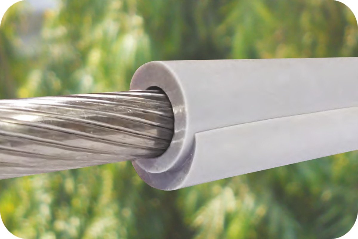
Gala Silicon Overhead Line Covers are made from high quality non-tracking silicon rubber that are designed for field installation over bare conductors. These covers provide a layer of electrical insulation for Phase-to-Phase and Phase-to-Ground protection from bird and animals. The GSOC provides electrical insulation, UV resistance and tracking resistance. Silicon Self-fusing Tape can be applied on it for better insulation.
Features & Benefits
- Excellent UV and Ozone resistance.
- Excellent Tracking resistance.
- Good Di-electric strength.
- Protection for leads and jumpers.
- Highly flexible silicone tubing makes application easy.
- Flame Retardant.
- No special installation tool required.
- Does not require further derating conductors.
- Helps prevent contacts by eliminating gaps in coverage.
- Provides Insulation Enhancement upto 765 kV
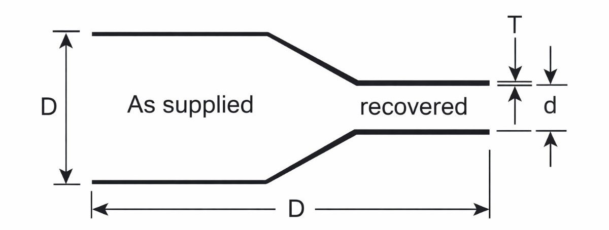
Diagram
Selection Chart – GSOC-M (Upto 12kV)
| Gala Code | Conductor Size in Dia. (mm) | Thickness (mm) | Packaging (Mtr./Roll) |
|---|---|---|---|
| GSOC-M 15 | Upto 15 | 2.0 | 15 |
| GSOC-M 20 | Upto 20 | 2.0 | 15 |
| GSOC-M 24 | Upto 24 | 2.0 | 15 |
| GSOC-M 32 | Upto 32 | 2.0 | 15 |
| GSOC-M 38 | Upto 38 | 2.0 | 15 |
Selection Chart – GSOC-H (Upto 36kV)
| Gala Code | Conductor Size in Dia. (mm) | Thickness (mm) | Packaging (Mtr./Roll) |
|---|---|---|---|
| GSOC-H 15 | Upto 15 | 2.7 | 15 |
| GSOC-H 20 | Upto 20 | 2.7 | 15 |
| GSOC-H 24 | Upto 24 | 2.7 | 15 |
| GSOC-H 32 | Upto 32 | 2.7 | 15 |
| GSOC-H 38 | Upto 38 | 2.7 | 15 |
Selection Chart – GSOC-H3 (Upto 36kV)
| Gala Code | Conductor Size in Dia. (mm) | Thickness (mm) | Packaging (Mtr./Roll) |
|---|---|---|---|
| GSOC-H3- 15 | Upto 15 | 3.0 | 15 |
| GSOC-H3- 20 | Upto 20 | 3.0 | 15 |
| GSOC-H3- 24 | Upto 24 | 3.0 | 15 |
| GSOC-H3- 32 | Upto 32 | 3.0 | 15 |
| GSOC-H3- 38 | Upto 38 | 3.0 | 15 |
Selection Chart – GSOC-EH (Upto 765kV)
| Gala Code | Conductor Size in Dia. (mm) | Thickness (mm) | Packaging (Mtr./Roll) |
|---|---|---|---|
| GSOC-EH 15 | Upto 15 | 5.0 | 15 |
| GSOC-EH 20 | Upto 20 | 5.0 | 15 |
| GSOC-EH 24 | Upto 24 | 5.0 | 15 |
| GSOC-EH 32 | Upto 32 | 5.0 | 15 |
| GSOC-EH 38 | Upto 38 | 5.0 | 15 |
Technical Specification
| Properties | Test Method | Typical Value |
|---|---|---|
| Physical | ||
| Tensile Strength | ASTM D638 | 7 N/mm² (min.) |
| Elongation | ASTM D638 | 300% (min.) |
| Water Absorption | ASTM D570 | 0.5 (max.) |
| Low Temp. Install at 0°C | – | Installable without difficulty |
| Thermal | ||
| Air Ageing | ASTM D2671 | 150°C for 168 Hrs. |
| Tensile Strength | ASTM D638 | 3.5 N/mm² (min.) |
| Elongation | ASTM D638 | 150% (min.) |
| Electrical | ||
| Dielectric Strength | ASTM D149 | >210 kV/cm |
| Volume Resistance | ASTM D257 | 1 x 10¹³ Ohm.cm (min.) |
| Tracking and Erosion Resistance | ASTM D2303 |
No tracking or erosion to top surface or flame failure after: • 1 hr. at 2.5 kV • 1 hr. at 2.75 kV • 1 hr. at 3.0 kV • 20 min. at 3.25 kV |
* The above mentioned values are typical analytical values obtained on material when tested as per applicable standards under controlled laboratory conditions and should not be construed as Specifications for the product.
Certificates


FAQs
1. What is a Heat Shrink Shroud?
A Heat Shrink Shroud is a protective sleeve made from cross-linked polymer material that shrinks when heat is applied. It provides insulation, sealing, and mechanical protection for cables, joints, and terminations.
2. How does a Heat Shrink Shroud work?
When heat is applied using a heat gun or torch, the shroud shrinks uniformly and tightly wraps around the cable or joint, creating a secure and sealed covering.
When heat is applied using a heat gun or torch, the shroud shrinks uniformly and tightly wraps around the cable or joint, creating a secure and sealed covering.
3. What material is Heat Shrink Shroud made of?
It is typically made from cross-linked polyolefin material, often containing carbon black for UV resistance and weather protection.
Related Products
")
Polyolefin Overhead Line Cover
")
Polyolefin Overhead Line Cover

Polyolefin Overhead Line Cover
Enquiry
109+
Countries
Served

40+
Years
In Industry

1250+
Kw
Solar Generative

225000
Area
Sq ft