Heat Shrink Bus Bar Sleeve
Products
- Heat Shrinkable Joints & Terminations
- Insulation Enhancement Product
- Screened Separable Connectors
- Heat Shrinkable Moulded Shapes
-
Heat Shrink Tubes / Sleeves
- Advantages Of Heat Shrink Tubing
- Thin Wall Tubes
- GDW : Dual Wall Tubing
- Medium/Heavy Wall Tubes-Commercial
- Heat Shrink Co-extruded Tubing Premium Quality
- Red Insulation Tubes
- Non Tracking Tubes
- Busbar Sleeves
- Stress Control Tube
- Non Tracking Tubes
- Integrated Stress Control Tube-GVOT Tube
- Heat Shrink Double Layer Tube-GDTL Tube
- High Shrink Ratio Heat Shrink Tube
-
Switchgear Insulation Products
- Barrier Board Sheet
- End Sealing Kit for Extensible RMU/GIS Bushing
- Heat Shrink Bus Bar Sleeve
- Bus Bar Insulating Shrouds
- Bus Bar Insulating Shrouds Polyolefin
- Bus Bar End Caps
- Thin wall tube wire marking
- Heat Shrink Tape (Bustape)
- Insulation for Circuit Breakers
- Busbar Sleeve for 66 kV
- Bushing Boot
- Non Shrinkable High Voltage Tape
- Heat Shrinkable Gland
- Cable Sealing & Repair Products
- Silicone Overhead Line Cover
- Polyolefin Overhead Line Cover (Insulcover)
- Overhead Line Tube (Insulcover)
- Pipeline / Corrosion / Cathodic Protection Products
- Pole Protection Products
- Wire Harness Products
- New Products
- Miscellaneous

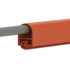
Bus Sleeve is heat shrinkable busbar Sleeve designed to insulate busbar system up to 36kV & to protect against accidental flash-over. The Sleeve are manufactured from high quality cross-linked polyolefin material. Meet ANSI C37.20.2 standard for MV switchgear application up to 36kV.
Features & Benefits
- Reduce Busbar clearance.
- Prevent Busbar from chemical corrosion effected by strong acid, alkali, salt etc.
- Solve the problem of insulation among Busbar in Bus Duct.
- Halogen free, flame retardant.
- High dielectric strength.
- Highly Flexible for use on straight or angled bars without creasing.
Applications
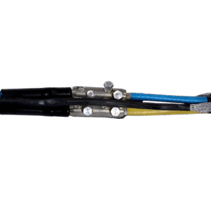
- Ideal for applications where there is a large dimensional difference between the cables, connectors and components.
- Enables the Tube to cover the large-size transi ons between cables, cable connectors and back shells, thus simplifying repairs of damaged cable as well as sealing the back end of the connectors.
Diagram

Selection Chart – Thin Wall Tube [Up to 3.3KV]
| Gala Size | D | d | T (±10%) | Reel Length | Rectangular Bars (W+B) | Round Bar Ø mm | ||
|---|---|---|---|---|---|---|---|---|
| mm (min.) | mm (max.) | mm | mtrs | Min. | Max. | Min. | Max. | |
| GSC 16/8 | 16 | 8 | 0.69 | 100 | 16 | 18 | 12 | 12 |
| GSC 20/10 | 20 | 10 | 0.78 | 100 | 22 | 25 | 14 | 16 |
| GSC 30/15 | 30 | 15 | 0.86 | 50 | 33 | 38 | 21 | 24 |
| GSC 40/20 | 40 | 20 | 0.96 | 50 | 44 | 52 | 28 | 33 |
| GSC 50/25 | 50 | 25 | 0.96 | 25 | 53 | 65 | 34 | 41 |
| GSC 60/30 | 60 | 30 | 0.96 | 25 | 64 | 75 | 41 | 48 |
| GSC 70/35 | 70 | 35 | 1.10 | 25 | 72 | 90 | 46 | 57 |
| GSC 80/40 | 80 | 40 | 1.27 | 25 | 86 | 100 | 55 | 64 |
| GSC 100/50 | 100 | 50 | 1.40 | 25 | 104 | 125 | 66 | 80 |
| GSC 120/60 | 120 | 60 | 1.40 | 25 | 110 | 150 | 70 | 96 |
| GSC 150/75 | 150 | 75 | 1.40 | 25 | 151 | 190 | 96 | 121 |
| GSC 180/90 | 180 | 90 | 1.50 | 25 | 179 | 236 | 114 | 150 |
Selection Chart – Medium Wall Tube [Upto 24KV]
| Gala Size | D | d | T (±10%) | Reel Length | Rectangular Bars (W+B) | Round Bar Ø mm | ||
|---|---|---|---|---|---|---|---|---|
| mm (min.) | mm (max.) | mm | mtrs | Min. | Max. | Min. | Max. | |
| GMB 16/6 | 16 | 6 | 1.70 | 25 | 11 | 18 | 7 | 12 |
| GMB 25/10 | 25 | 10 | 2.50 | 25 | 16 | 30 | 12 | 20 |
| GMB 30/12 | 30 | 12 | 2.10 | 25 | 25 | 38 | 16 | 25 |
| GMB 40/16 | 40 | 16 | 2.10 | 25 | 33 | 50 | 21 | 32 |
| GMB 50/20 | 50 | 20 | 2.10 | 25 | 38 | 63 | 24 | 40 |
| GMB 65/25 | 65 | 25 | 2.20 | 25 | 53 | 82 | 34 | 52 |
| GMB 75/28 | 75 | 28 | 2.50 | 25 | 63 | 94 | 40 | 60 |
| GMB 85/32 | 85 | 32 | 2.50 | 25 | 69 | 107 | 44 | 68 |
| GMB 100/38 | 100 | 38 | 3.00 | 25 | 83 | 126 | 53 | 80 |
| GMB 120/45 | 120 | 45 | 3.00 | 25 | 104 | 150 | 66 | 96 |
| GMB 150/60 | 150 | 60 | 3.30 | 20 | 132 | 200 | 84 | 127 |
| GMB 180/72 | 180 | 72 | 3.00 | 15 | 151 | 226 | 96 | 144 |
| GMB 205/85 | 210 | 84 | 3.10 | 1.5 | 239 | 257 | 152 | 164 |
| GMB 250/100 | 250 | 100 | 3.10 | 1.5 | 264 | 314 | 168 | 200 |
Selection Chart – Heavy Wall Tube [upto 36KV]
| Gala Size | D | d | T (±10%) | Reel Length | Rectangular Bars (W+B) | Round Bar Ø mm | ||
|---|---|---|---|---|---|---|---|---|
| mm (min.) | mm (max.) | mm | mtrs | Min. | Max. | Min. | Max. | |
| GHB 25/8 | 25 | 8 | 3.20 | 25 | 20 | 28 | 13 | 20 |
| GHB 30/12 | 30 | 12 | 3.50 | 25 | 28 | 33 | 18 | 25 |
| GHB 40/16 | 40 | 16 | 3.50 | 25 | 35 | 45 | 22 | 32 |
| GHB 50/20 | 50 | 20 | 3.50 | 25 | 45 | 54 | 29 | 40 |
| GHB 65/25 | 65 | 25 | 3.50 | 25 | 50 | 62 | 32 | 43 |
| GHB 75/28 | 75 | 28 | 3.50 | 20 | 53 | 69 | 34 | 47 |
| GHB 85/32 | 85 | 32 | 3.50 | 20 | 69 | 100 | 44 | 68 |
| GHB 100/38 | 100 | 38 | 3.70 | 20 | 83 | 102 | 53 | 72 |
| GHB 120/45 | 120 | 45 | 3.70 | 20 | 94 | 125 | 60 | 85 |
| GHB 150/60 | 150 | 60 | 3.70 | 15 | 122 | 168 | 78 | 105 |
| GHB 180/70 | 180 | 70 | 3.70 | 15 | 160 | 196 | 102 | 125 |
| GHB 205/85 | 205 | 85 | 3.70 | 1.5 | 239 | 250 | 152 | 164 |
| GHB 250/120 | 250 | 120 | 4.20 | 1.5 | 264 | 314 | 168 | 200 |
Technical Specification
| Test Description | Recorded Value | Test Method |
|---|---|---|
| Physical | ||
| Tensile Strength | 9 N/mm² (MPA)(min.) | ASTM D638 |
| Ultimate Elongation | 350% (min.) | ASTM D638 |
| Water Absorption | 0.5 % (max.) | ASTM D570 |
| Density | 1.20 ± 0.2 gm/cm³ | ASTM D792 |
| Hardness | 45 ± 10 Shore D | ASTM D2240 |
| Thermal | ||
| Accelerated Ageing | (150°C for 1200 Hrs) | IEC 60684-2 |
| Tensile Strength | 7.7 N/mm² (Mpa) | ASTM D 638 |
| Ultimate Elongation | 300 % (Min.) | ASTM D638 |
| Low Temperature Flexibility (-40°C for 4 Hrs.) | No Cracking | ASTM D2671 |
| Heat Shock (250°C for 30 Min.) | No Cracking or flowing | ESI 09-11 |
| Shrink Temperature | 125°C | IEC 216 |
| Continuous Temperature limit | -40°C to +115°C | IEC 216 |
| Electrical | ||
| Dielectric Strength | 22 KV/mm. (Min.) | ASTM D149 |
| Volume Resistivity | 1 x 10¹³ Ohm.cm (min.) | ASTM D257 |
| Dielectric Constant | 5 (Max.) | ASTM D150 |
Clearance With Insulation
| Voltage | Medium Wall Tube (GMB) | Heavy Wall Tube (GHB) | Un-Insulated Busbars (mm) as per IEC 71-2 | ||||||
|---|---|---|---|---|---|---|---|---|---|
| PH to PH (mm) | PH to GR (mm) | PH to PH (mm) | PH to GR (mm) | ||||||
| Rectangular | Round | Rectangular | Round | Rectangular | Round | Rectangular | Round | ||
| 12 kV | 65 | 55 | 57 | 65 | 35 | 30 | 45 | 40 | 120 |
| 17.5 kV | 85 | 70 | 105 | 85 | 55 | 50 | 65 | 60 | 160 |
| 24 kV | 115 | 95 | 150 | 125 | 70 | 60 | 100 | 90 | 220 |
| 36 kV | 200 | 150 | 285 | 205 | 140 | 130 | 190 | 180 | 320 |
Certificates


FAQs
1. What is a Heat Shrink Shroud?
A Heat Shrink Shroud is a protective sleeve made from cross-linked polymer material that shrinks when heat is applied. It provides insulation, sealing, and mechanical protection for cables, joints, and terminations.
2. How does a Heat Shrink Shroud work?
When heat is applied using a heat gun or torch, the shroud shrinks uniformly and tightly wraps around the cable or joint, creating a secure and sealed covering.
When heat is applied using a heat gun or torch, the shroud shrinks uniformly and tightly wraps around the cable or joint, creating a secure and sealed covering.
3. What material is Heat Shrink Shroud made of?
It is typically made from cross-linked polyolefin material, often containing carbon black for UV resistance and weather protection.
Related Products
Polyolefin Overhead Line Cover

Polyolefin Overhead Line Cover
Polyolefin Overhead Line Cover
Enquiry
109+
Countries
Served

40+
Years
In Industry

1250+
Kw
Solar Generative

225000
Area
Sq ft