Cold Shrink Tubing - EPDM
Products
- Heat Shrinkable Joints & Terminations
- Insulation Enhancement Product
- Screened Separable Connectors
- Heat Shrinkable Moulded Shapes
-
Heat Shrink Tubes / Sleeves
- Advantages Of Heat Shrink Tubing
- Thin Wall Tubes
- GDW : Dual Wall Tubing
- Medium/Heavy Wall Tubes-Commercial
- Heat Shrink Co-extruded Tubing Premium Quality
- Red Insulation Tubes
- Non Tracking Tubes
- Busbar Sleeves
- Stress Control Tube
- Non Tracking Tubes
- Integrated Stress Control Tube-GVOT Tube
- Heat Shrink Double Layer Tube-GDTL Tube
- High Shrink Ratio Heat Shrink Tube
-
Switchgear Insulation Products
- Barrier Board Sheet
- End Sealing Kit for Extensible RMU/GIS Bushing
- Heat Shrink Bus Bar Sleeve
- Bus Bar Insulating Shrouds
- Bus Bar Insulating Shrouds Polyolefin
- Bus Bar End Caps
- Thin wall tube wire marking
- Heat Shrink Tape (Bustape)
- Insulation for Circuit Breakers
- Busbar Sleeve for 66 kV
- Bushing Boot
- Non Shrinkable High Voltage Tape
- Heat Shrinkable Gland
- Cable Sealing & Repair Products
- Silicone Overhead Line Cover
- Polyolefin Overhead Line Cover (Insulcover)
- Overhead Line Tube (Insulcover)
- Pipeline / Corrosion / Cathodic Protection Products
- Pole Protection Products
- Wire Harness Products
- New Products
- Miscellaneous


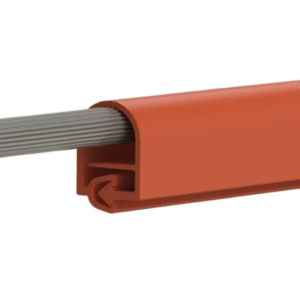
Gala Cold Shrink Tube are open ended, tubular rubber sleeves that are factory expanded and assembled onto a removable core. The core is removed after the tube has been position for installation over and inline connection, terminal lug etc. allowing the tube to shrink and form a water resistance seal. The insulating tube is made of high quality EPDM Rubber which does not contain chloride or sulfur. Seven diameter sizes will cover range of cable upto 1100 volts for copper and aluminium conductor upto 1000 Sq. mm.
Features and Benefits
- Simple and fast installation, no tools required.
- Accommodates a wide range of cable sizes.
- Seals tight, retains resiliency for years.
- Water resistance.
- No mastic or tape required.
- Resists acids and alkalis.
- Resists ozone.
- Resists fungus.
- Good thermal stability
- Operating temperature range -40 °C to 105°C
- Water resistance, meets the water seal requirements of ANSI C119.1
Diagram

Selection Chart
| Part Number / Size | Supplied I.D. (mm) | Recovered I.D. (mm) | Recovered Wall Thickness (mm) | Spools Mtr./Spool |
|---|---|---|---|---|
| GPTFE 1.0/0.6 | 1.0 | 0.6 | 0.20 | 200 |
| GPTFE 1.5/0.9 | 1.5 | 0.9 | 0.20 | 200 |
| GPTFE 2.0/1.3 | 2.0 | 1.3 | 0.20 | 200 |
| GPTFE 2.5/1.5 | 2.5 | 1.5 | 0.20 | 200 |
| GPTFE 3.0/1.8 | 3.0 | 1.8 | 0.20 | 200 |
| GPTFE 3.5/2.0 | 3.5 | 2.0 | 0.20 | 100 |
| GPTFE 4.0/2.5 | 4.0 | 2.5 | 0.25 | 100 |
| GPTFE 4.5/2.8 | 4.5 | 2.8 | 0.25 | 100 |
| GPTFE 5.0/3.0 | 5.0 | 3.0 | 0.25 | 100 |
| GPTFE 6.0/3.8 | 6.0 | 3.8 | 0.25 | 100 |
| GPTFE 7.0/4.0 | 7.0 | 4.0 | 0.25 | 100 |
| GPTFE 8.0/4.8 | 8.0 | 4.8 | 0.25 | 1 |
| GPTFE 9.0/5.0 | 9.0 | 5.0 | 0.30 | 1 |
| GPTFE 10.0/5.8 | 10.0 | 5.8 | 0.30 | 1 |
| GPTFE 11.0/6.4 | 11.0 | 6.4 | 0.30 | 1 |
| GPTFE 12.0/7.0 | 12.0 | 7.0 | 0.30 | 1 |
| GPTFE 13.0/7.5 | 13.0 | 7.5 | 0.35 | 1 |
| GPTFE 14.0/8.0 | 14.0 | 8.0 | 0.35 | 1 |
| GPTFE 15.0/8.5 | 15.0 | 8.5 | 0.40 | 1 |
| GPTFE 16.0/9.0 | 16.0 | 9.0 | 0.40 | 1 |
*All dimensions are in mm. d,D : Internal Diameter.
Technical Specification
| Properties | Test Methods | Typical Value |
|---|---|---|
| Colour | Visual | Black |
| 300% Modulus | ASTM D-412 | 3.3 MPa |
| Ultimate Tensile | ASTM D-412 | 9.6 MPa |
| Ultimate Elongation | ASTM D-412 | 750% |
| Die C Tear | ASTM D-624C | 26.3 KN/m |
| Fungus Resistance | ASTM G-21 | 28 Days exposure no growth |
| Moisture Absorption 7 days @ 90°C H₂O | Internal Method | Wt. Gain 1.8% |
| Dielectric Strength | ASTM D149 | 14.3 kV/mm |
Certificates


FAQs
1. What is a Screened Separable Connector?
A Screened Separable Connector is a medium-voltage cable accessory used to connect power cables to transformers, switchgear, or other equipment. It is fully screened and separable, allowing safe installation, disconnection, and maintenance.
2. What voltage levels are Screened Separable Connectors used for?
They are commonly used for 3.6 kV to 36 kV medium-voltage applications, depending on the connector design and standards.
3. Where are Screened Separable Connectors typically used?
Related Products
Polyolefin Overhead Line Cover
Polyolefin Overhead Line Cover
Polyolefin Overhead Line Cover
Enquiry
109+
Countries
Served

40+
Years
In Industry

1250+
Kw
Solar Generative

225000
Area
Sq ft